

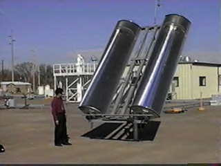
Continuing in his effort to assist industry in the implementation of his cyber-progeny, Mr. Maish, pictured to the left with an Entech Corporation 860 Watt linear Fresnel concentrator, produced yet another version of his controller that ran off of batteries charged by a similar 5-watt panel (near the center of the frame) and consuming only an average (including the intermittant motor-on power) 12 milliamps of current throughout the day. These units were capable of running for months and even years in remote areas without the need of human intervention.
Part of the reason the units could maintain operation and accuracy for such long periods was the implementation of clock correction algorithms that systematically adjusted the time of day by a few seconds per day and another few seconds per week. Proper calibration of those correction values produced clock accuracies in the neighborhood of less than a minute per year of error. To further improve on that accuracy, an additional, seasonal correction for average temperature changes across winter and summer was included, bringing the error down to less than 30 seconds per year.
This basic controller technology has been designed to accomodate most mechanical positioning geometries. The four basic geometries are Azimuth/Elevation, where the primary axis (the one fixed to the Earth) is coincident with a line running through the center of the Earth, Polar/Declination, where the primary axis is parallel to the Earth's axis of rotation, and two Tilt/Roll versions, one with the primary axis aligned East-West and the other North-South. In all cases the secondary axis is orthogonal (perpendicular) to and rotates about the primary axis allowing the positioner to point anywhere in 3-dimentional space within the physical limitations of the mechanical range of motion.
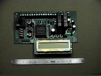
In order to define the mathematical characterization of these various geometries, the size and the position (orientation) with respect to the Earth, there are actually over one hundred parameters that are stored in non-volitile (won't go away when the power is off) memory within the MCU. Most of these parameters are defined when the SolarTrak® is configured for a particular mechanical device but several are specific to where in the world that device will be installed.
The bulk of these parameters are set using a serial interface with either a PC running special software or a companion board (teaching pendant) referred to as the User Interface Module (UIM). The remaining, site-specific parameters and several calibration settings are accessible through the use of the LCD monitor and three buttons located just above the monitor anf to the right of the MCU. These three buttons funtion in a fashion very similar to a digital watch where the 'Item' button chooses which parameter to view, the 'Adjust' button selects the parameter for modification and the 'Value' button actually changes the number.
This version of the SolarTrak® Control board has become the foundation of all subsequent control system designs built by EEInc. When power requirements exceed the low-power limits of the basic board, a higher power motor interface circuit is included to accomodate the needs of large systems.