SolarTrak®
Development Milestones
Page
3 - Complex Control Strategies
The real strength of using a computer to do sun-tracking control is not just
that the device stays right on sun without wandering due to haze or reflections,
but that it can perform other functions related to the energy-collection process
at the same time. Much like the 'Backtracking'
control strategy, the computer can keep the current sun position 'in mind',
using it as a reference but not necessarily pointing right at it.
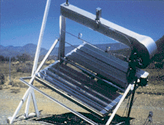
The device to the right, the DSET EMMAQUA™ unit, used for accelerated
weathering applications, requires several functions to be attended to at once
in order to perform its intended job. The device is a concentrator using a
linear Fresnel-type of reflective concentration. Ten flat strips of mirror,
coated with a special limited-spectrum first-surface (on top of the glass
instead of behind it like regular mirrors) reflective surfacing to overlay
(concentrate) ten strips of light on the underside of its air plenum (tunnel)
where paint samples and other materials are mounted.
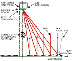
Since this much concentration will produce a great deal of heat as well as
the increased ultraviolet radiation, the samples must be cooled to keep them
from burning up. An air blower pressurizes the plenum and forces air out of
a slit along the mounting surface offering continuous air-cooling of the samples.
While everything is working properly, the samples are exposed to environmental
conditions at higher than normal levels and observational data is collected
at regular intervals, however, if the AC power for the blower fails, the samples
can burn up, invalidating the data collection process.
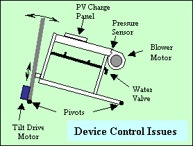
In order to protect the device from such disasters, a pressure sensor is
mounted in the plenum that will change state (On or Off) as the air pressure
rises above a certain level. By monitoring this sensor, the computer can decide
whether or not to focus directly on the sun. If the pressure is low, the computer
will actually PREVENT the unit from focussing.
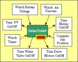
To start up the unit, several sensor checks must be performed, passed and
repeated continuously throughout the control process.
1. The battery voltage, which powers the controller, must be high enough.
If it is low, the PV is turned on to charge it. If it stays low, the controller
will keep the device in a stow position or move to that position if it is
already tracking.
2. The controller computes the sun position. If the Sun is above the horizon
the controller will proceed to check everything else and put the device on
sun after all the sensor checks are satisfied.
3. The air pressure must be high enough. If it is not the controller turns
on the blower using an AC solid-state relay (SCR) controlled by a low-voltage
(12 volts) DC control signal to activate the circuit. If the pressure stays
low,
the unit remains in stow. If the the AC power fails and the pressure drops,
the controller rolls the secondary axis (powered by the battery), off-sun
to prevent damage to the test samples.
Once these steps are satisfied, the controller drives the unit on sun.
While the device is actively focussing the concentrated sunlight on the samples,
the controller uses its real-time clock to sytematically spray water (de-ionized
to prevent contamination by calcium and other elements) for a prescribed period
of time at pre-defined intervals. This process mimics the effect of rain on
specimens typically found outdoors.
The AC blower motor and the water spray On-Off valve are controlled by the
SolarTrak® using solid-state relays activated by a 14-volt signal. It
was discovered early on that a lower voltage would not succeed in turning
the SCR on 'HARD' enough to conduct sufficient current to operate larger motors.
Description and Diagrams of Backtracking
There
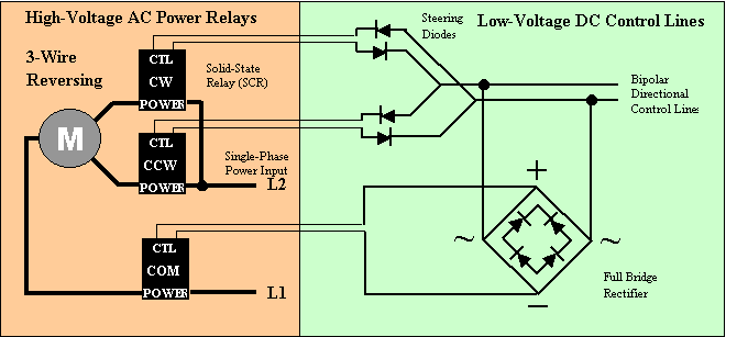
are two basic types of single-phase AC motor reversing circuits. The first has
a common leg (neutral) and two hot legs, one for each direction. Only one hot
leg is used at a time along with the neutral. In order to do this the controller
activates one of two SCR's depending on the required direction of rotation.
In order to select between the two SCR's without a mechanical switch, steering
diodes are used. Diodes allow current to flow in only one direction, blocking
it in the other. The arrows in the schematic indicate the direction of
Although
no actual current flows when the neutral is left connected while the motor is
off, safety considerations make it desireable to switch the neutral leg, a modification
made in all versions since 1999. Since the neutral (common) leg is turned on
regardless of the selected direction, it is necessary to 'rectify' the bipolar
control signal such that it always matches the 'ON' polarity of the third SCR.
A 'full-bridge' rectifier is used to accomplish this task. The internal components,
effectively four diodes arranged as shown, take the bipolar signal as input
on the 'AC' input terminals indicated by the '~' character and allow current
to flow such that the output terminals (+ & -) always have the same polarity.
current flow allowed by that device. By using them in pairs, as shown, a particular
polarity (in this case at about 14 volts DC) placed on the control lines by
the SolarTrak® bipolar motor driver outputs will match only one of the two
pairs of diodes and allow that one to conduct while the other pair blocks the
current flow. The SCR's are 'turned on' by applying this voltage such that a
few milliamps of current will flow across the terminals labelled 'CTL'. If current
is not allowed to flow, they won't turn on. Once that voltage is applied and
current begins to flow, the two terminals labelled 'POWER' will begin to conduct
current to that motor leg. The SCR will then remain 'ON' until the control voltage
goes back to zero and the DC current on the CTL terminals stops.
The
second type of AC reversing circuit is refered to here as a 4-wire circuit,
so called because it involves both the two single-phase power inputs, L1 and
L2, and a pair of capacitor leads which actually accomplish the directional
control. As it happens, the capacitor leads are in series with L2 and so turning
off both capacitor leads also turns off the L2 leg. The 4-wire version requires
the two capacitor leads to be swapped to accomplish the reversing function.
The capacitor produces the reversing effect by shifting the phase relationship
of the two motor windings according to the polarity of the capacitor inputs.This
configuration makes use of an AC H-Bridge composed of four SCR's where two at
a time (one for each capacitor lead) are used for each direction. Turning off
all four of the SCR's interrupts power on the L2 leg, then the use of a fifth
SCR will kill the power on L1. At the risk of confusion, this exact circuit
is also used for reversing a 3-phase motor. The only real difference is that
a 3-phase motor has three phase legs instead of the two for single-phase and
requires any two of the phase legs to be swapped in order to accomplish the
reversing function. Having all three phases as inputs replaces the need for
a capacitor, dramatically increasing the motor efficiency and reducing heat.
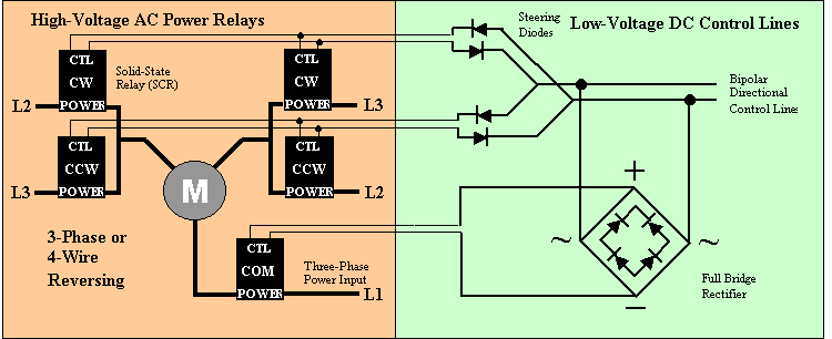
The
implementation of the 4-wire, single phase and the 3-phase configurations simply
requires two interpretations (labelling conventions) for the same connection
terminals. In each case two SCR's are turned on for each rotational direction
by 'daisy-chaining' the control signal output from the steering diode pairs.
The same full-bridge rectifier is used to control the fifth relay. The connections
labelled as L2 and L3 are swapped from one pair of SCR's to the next. The 4-wire
circuit uses L2 and L3 for the capacitor leads and the 3-phase version simply
uses the second anf third legs.
