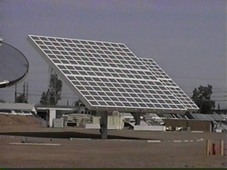


In 1997, one of these Amonix 250x Fresnel concentrators was in need of a new controller. Using the Martin-Marietta solution as a basis, a high-power DC version of the SolarTrak® controller was developed. Not without incident.
The payload of this unit is about 19000 pounds and measures 30' high by 40' wide and 2' thick. The motors are DC, permanent magnet type, 1/4-horsepower and run off of rectified 115 VAC power. Each motor needs an H-Bridge to swap the polarity of the two DC leads and allow reversability.
The required tracking accuracy of these units was +/- 0.1 degrees.
As was soon found, the amount of backlash in both the azimuth and elevation drive trains, almost precluded the successful tracking of the Sun but a calibration process included in the tracking codes allowed an effective error correction formula to be derived from empirical data.
%20High%20Power%20DC%20Controller%20unit%201-3.jpg)
Of even greater concern in the necessary tracking control strategy was the weight of the payload which, when approaching the horizon, placed so much tensile force on the elevation ball-screw actuator that it would back-drive the screw and (if not stopped) would allow the payload to accelerate downward, impactng with the pedestal column. It didn't even matter whether the unit was moving up or down when the power was turned off, it took off downward in any event.
The solution, based on the fact that it uses the permanent magnet motors, was to short the motor leads when it was supposed to be off. If such a motor is turned mechanically it reacts as a generator, producing electricity of a polarity opposed to the mechanical rotation. With the leads shorted, any mechanical motion of the motor generates an electric current that opposes the motion and stops itself. Although small, slow motions can occur, this dynamic brake will prevent catastrophies even in a power failure.
The following schematic of a DC H-bridge utilizes the same principle as the AC version. With DC, only the two motor leads must be controlled so the fifth solid-state relay is unnecessary, however, if a dynamic brake is used on one or both axes, the same full-bridge-rectifier circuit is used to control it.
The same steering diodes are used to differentiate between the two pairs of solid-state relays, this time MOSFET's rather than SCR's.
Rather than controlling a fifth solid-state relay, the full-bridge-rectifier circuit energizes a mechanical, double-pole, double-throw relay that can handle the high voltage and current.
The eccentric load shown to the left occurs when the CG of the payload goes past the plane of the axis of rotation (dotted line). When great enough, unintended motion can occur without the dynamic brake circuit.
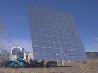
The large area mirror (150 Sq-meters), at Sandia National Laboratories, to the right, uses the same geardrive and requires the same brake circuit for proper operation although the weight of the glass mirror and its structure is far less than the concentrator.